Trouble with the sound module & building other droids

My last post was from January and not much has happened since then – at least not much on R3-B9. One the essential features is, of course, the sound. I had played with an SD card reader module for Arduino and also with a micro SD card reader like this one.

microsdcard
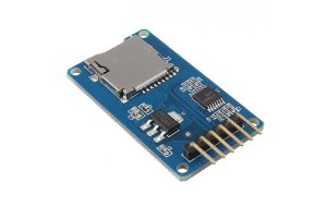
While I was able to read a text file from the SD card, I did not succeed in playing mp3 files. This does not come totally unexpected, as many people seem to have trouble getting this module to work (… but then there are also many people who got it working …). It is a little sad, since this was such a cheap solution (aliexpress.com has this module for $0.51).

But now I hope that I found an alternative solution with this “DFPlayer Mini” module.

Currently I am waiting for this to arrive from aliexpress.com (at $2.15 this is slightly more expensive – especially if you plan to use this in a number of other projects too).

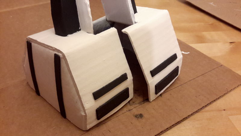
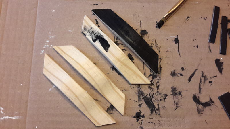
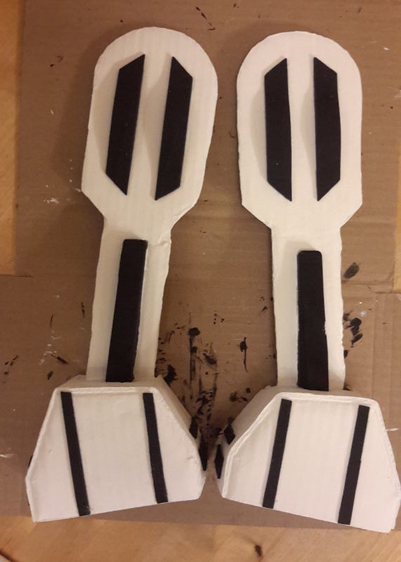
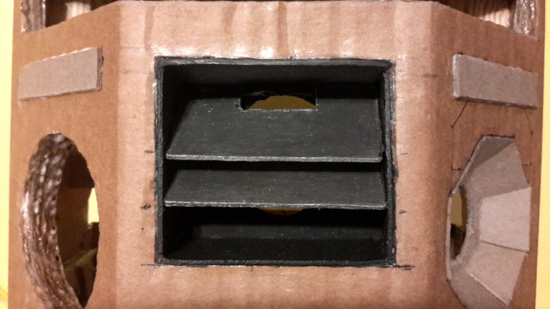
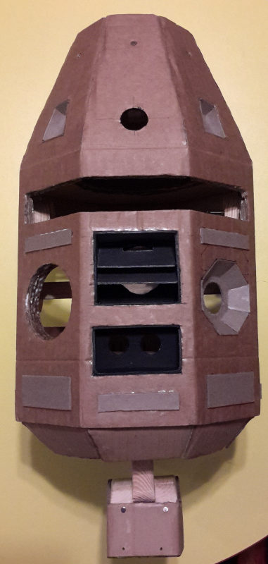
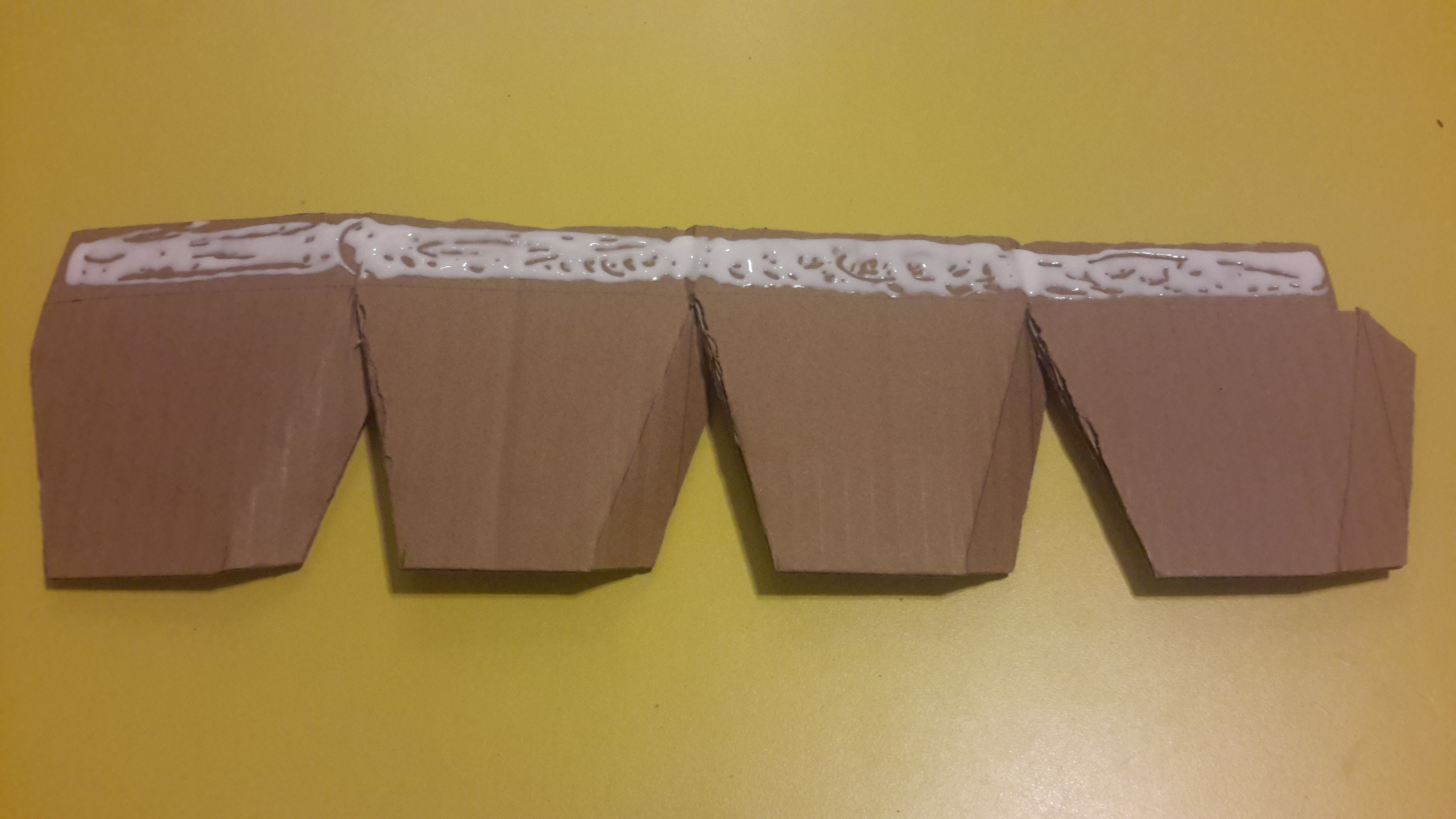
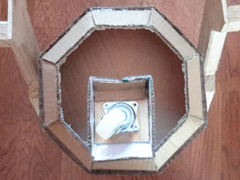
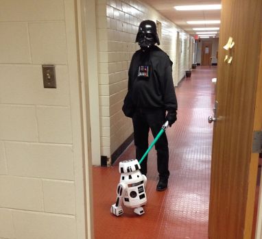
In the meantime, however, I made good progress with a few other droids: For my daughter I built another astromech, X7-OB (as requested: without motors, but maybe later with some lights and sounds), for my son I build a mousedroid MSE-6c, and then, in “The Force Awakens”, I noticed that new white droid on the Star destroyer, sentry droid H015, and I started that one too.

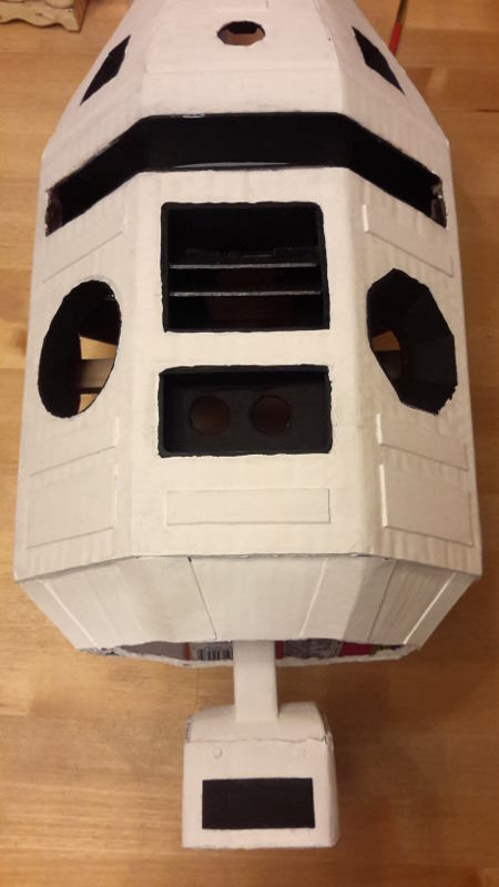
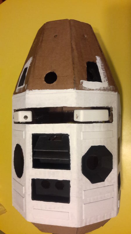
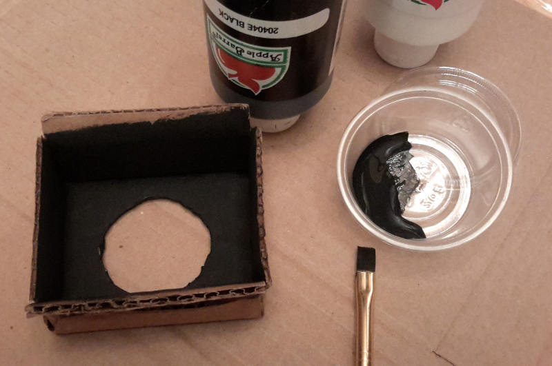
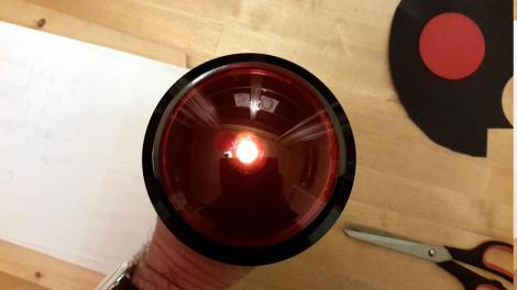
As if this wasn’t enough, I have now also started building a HAL 9000 replica – here is a first photo of the eye.

hal006

While there is still plenty of work to do with H015 and HAL, sooner or later all these projects will be waiting for the sound module. I really hope that I can get the DFPlayer module to work.

R3-B9’s first Christmas

Over Christmas, I made a first video of R3-B9 in motion wearing a Santa hat in front of our Christmas tree.

After a phase of more activity in December (to get R3-B9 ready by the start of TFA), I expect future progress to be less fast. Only minor mechanical work remains to be done (mounting the sensors, the LEDs, the speaker, and the arms). Most work will be about testing and then soldering the circuits (including the microphone preamps and the shift registers for the LEDs), followed by the Arduino programming.

In the meantime I have promised to build further robots for my kids and, of course, they want their own blogs for this. So, here is the blog for my son’s MSE-6 mouse droid https://mousedroid.wordpress.com built at 83% of the original Star Wars version. And here is the blog for my daughter’s astromech droid X7-OB https://droidx7ob.wordpress.com which is a close relative to my R3-B9. But she wants it purely mechanical with no electronics, no Arduino, and no motors. However she really likes the idea of X7-OB being able to talk – so we have to see about this later…

First public appearance

Today, R3-B9 made its first public appearance! Yesterday night, I put some pieces together like the Arduino code for the motors (in the feet) and for the servo (for the head movement). I also inserted and connected one of the four center LEDs and a piezo, to have at least some light and sound. Everything was individually tested and worked. But when everything was combined, the motors stopped working. At first, I was afraid that some cables got disconnected in the “cable spaghetti” that I created on the preliminary breadboard setup. I thought I would never find that. But then I vaguely remembered something about clashes between Arduino libraries, and I googled “Arduino mega servo pin 44”. And right, the first search result http://playground.arduino.cc/Code/MegaServo revealed that using the servo.h library (which I did for the head servo) interferes with using pins 44/45 on the Arduino Mega for PWM (which I used for “enA” and “enB” of the L298N motor controller). Simple solution: I connected the motor controller to different Arduino pins, and everything worked – yeah! Although this is still far from the ultimate goal, the current state has enough “critical mass” to make it fun to watch and to start showing it around. My favorite mode of operation is when it turns on the spot while the head is turning forth and back and the LED is flashing.

And so, today I took my R3-B9 to my PHYS202 class and got a very nice reaction from my students (I should maybe mention, that initially I was hiding behind my son’s Darth Vader mask).

R3-B9-DarthVader-ed1

And tomorrow I will take my R3-B9 to the movie theater to watch its cousins BB-8 and R2-D2 in TFA.

Finishing the body – and the head

A few more layers of white and black paint and glossy coating are applied to the body and the legs. Now the motors and wheels are mounted to the legs and these are mounted to the body.

In the next step the neck assembly (with the head-servo and the lazy susan bearing) is fixed in the body.

Now it’s time to finish the head. The basic shape was already show in the post from October 5. Now I’m adding a wooden plate (on the inside – to mount this on the neck) and some further details. With a few layers of black and white paint, and three layers of gloss it looks like this.

Now the head is connected to the body and we get the first glimpse of the whole robot.

I love my R3-B9!

Adding details to body and legs

Here come the last details which are added to the body and the legs. To smooth the edges where the cardboard was glued at the bottom, I am adding eight pieces of cardboard to the corners. These hide the overlaps, and they provide some nice additional structure.

p50

While there is plenty of detail on the front side of my robot, the back side is still empty. Therefore I am adding three LEDs in a recessed mount (as used for the photo sensors and the microphones and also for the ultrasonic sensors).

p47 p48 p49

Finally, the legs are still a little boring. I am adding a few curved pieces of thin wood to the upper part, and a few strips of cardboard to the feet, all painted black.

p53 p52 p54 p55

Those were the last parts of the body – now it’s time for more layers of white and black paint and glossy coating.

Mounting the arms

After thinking about the possible features, I decided that my R3-B9 should have two servo-driven arms that sit inside the long horizontal slit in body, together with a bar of four white LEDs. The arms should have a blue LED on the front side, and two white LEDs on the inside, so they extend the four white center LEDs when the arms are opened. Here is the assembly of the arms:

p33 p34 p35 p36p40

The arms are fastened to micro servos which are mounted inside the body on wooden plates.

p37 p38 p39 p41

The provisional installation looks like this:

p42

In the second step, I build the mount for the four white center LEDs. The LEDs are not directly visible, but light through some white plastic (taken from a vinegar bottle).

p43 p44 p45 p46

I really love how this is coming together. Just a few more cosmetic details to add to the body and legs.

Adding the ultrasonic sensors and a speaker

The R3-B9 droid will have an obstacle-avoiding mode and also a wall-following mode. Therefore I am including three ultrasonic sensors HC-SR04 (available for 90 cents here) mounted at the bottom of the body, at the front and the two sides. This page has a very nice description of the sensor (but make sure to read the comment at the bottom by David, how to use the sensor in single-pin mode, and to use the “timeout” parameter in the Arduino code). I am using a recessed mount for the three ultrasonic sensors.

p25 p27 p26p29

To have some acoustic output, I am adding a 2″ speaker, powered by a little 3W amp PAM8403 (available here for 99 cents), mounted behind a vent-like cover.

p28 p30 p31 p32

Starting the body

During the last weeks I made some good progress on the mechanical structures for the robot’s body. You can not debate the beauty of R2-D2’s appearance, so it should look somehow like him. However, an original sized R2-D2 would be to big and heavy for the motors that came with my two wheel drive chassis. I also really want some artistic freedom in the design, so I chose to build R2-D2’s little brother. My kids helped me with the naming, and we agreed on the name “R3-B9”. Only later I learned that the R3 series exists in the Star Wars canon (http://starwars.wikia.com/wiki/R3-series_astromech_droid) and that my sketches are actually a little closer to the R4 series (http://starwars.wikia.com/wiki/R4-series_agromech_droid).

sk01

I decided to build the basic structures from cardboard and wood. The body has an octagonal shape with 9″ diameter.

p01 p02 p03 p04 p05

The two legs are made of plywood, with a wooden frame (the cover will later be made of cardboard). The third foot is made of wood.

sk02 sk04 sk05p06 p07 p08p09p10sk03sk07sk09p11p12p14p15

Putting everything together, this already has some personality (the head is not yet fixed to the body).

p16

In the next steps, I will make the covers for the legs and feet, add some conical shape to the bottom, and make openings in the body for the ultrasonic sensors, LEDs, and a speaker. Maybe I even add two small folding arms.

Hardware

More than two months have passed. During that time I have been on vacation, spent two weeks at CERN, and now I’m teaching summer school. The work on the robot is making little but constant progress. I have gathered lots of information on the web on different Arduino modules, refreshed my knowledge on electronics, and ordered plenty of stuff from Amazon, Dealextreme, and Ebay. The good thing is that I had plenty of time to wait for the cheap electronics components to be delivered from China or Hongkong which may take a handful of weeks.

I know, I got somehow carried away with my purchases, but I really plan to play around with my robot and implement plenty of features. I did quite some research to find the cheapest sources. Below is a list of what I got (so far).

Arduinos & connectors

mechanical components

modules

electronic parts